When an alternating voltage V1 is applied to a primary winding, an alternating current I1 flows in it producing an alternating flux in the core. As per Faraday’s laws of electromagnetic induction, an emf e1 is induced in the primary winding.
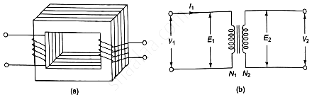
Working Principle of a transformer
e1 = \(-N_1\frac{d\varphi}{dt}\)
Where N1 is the number of turns in the primary winding. The induced emf in the primary winding is nearly equal and opposite to the applied voltage V1.
Assuming leakage flux to be negligible, almost the flux produced in primary winding links with the secondary winding. Hence, an emf e2 is induced in the secondary winding.
e2 = \(-N_2\frac{d\varphi}{dt}\)
Where N2 is the number of turns in the secondary winding. If the secondary circuit is closed through the load, a current I2 flows in he secondary winding. Thus energy is transferred from the primary winding to the secondary winding.
EMF EQUATION.
As the primary winding is excited by a sinusoidal alternating voltage, an alternating current flows in the winding producing a sinusoidally varying flux \(\varphi\) in the core.
\(\varphi\,=\,\varphi msin\omega t\)
As per Faraday’s law of electromagnetic induction an emf e1 is induced in the primary winding.
e1 = \(-N_1\frac{d\varphi}{dt}\)
e1 = \(-N_1\frac{d\varphi}{dt}\)(\(\varphi msin\omega t\))

Maximum value of induced emf = \(2\pi f \varphi_mN_1\)
Hence, rms value of induced emf in primary winding is given by,
E1 = \(\frac{Emax}{\sqrt2}\) = \(\frac{2\pi fN_1 \varphi_m}{\sqrt2}\) = 4.44fN1\(\varphi_m\)
Similarly rms value of induced emf in the secondary winding is given by,
E2 = 4.44\(fN_2\varphi_m\)
Also,\(\frac{E_1}{N_1}\) = \(\frac{E_2}{N_2}\) = 4.4f\(\varphi_m\)
Thus emf per turn is same in primary and secondary winding and an equal emf is induced in each turn of the primary and secondary winding.


