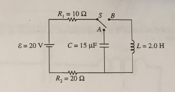
In the circuit shown above, the switch S is initially in the open position shown, and the capacitor is uncharged. A voltmeter, (not shown) is used to measure the correct potential difference across resistor R1. a. On the circuit diagram above, draw the voltmeter with the proper connections for correctly measuring the potential difference across resistor R1. b. At time t= 0, the switch is moved to position A. Determine the voltmeter reading for the time immediately after t= 0. c.After a long time, a measurement of potential difference across R1 is again taken. Determine for this later time each of the following. i.The voltmeter reading ii. The charge on the capacitor d. At a still later time t = T, the switch S is moved to position B. Determine the voltmeter reading for the time immediately after t = T. e. A long time after t = T, the current in R1 reaches a constant final value If. i. Determine If. ii. Determine the final energy stored in the inductor. f. Write, but do not solve, a differential equation for the current in resistor R1 as a function of time t after the switch is moved to position B.Read more on Sarthaks.com - https://www.sarthaks.com/1051124/the-circuit-shown-above-the-switch-initially-open-position-shown-the-capacitor-uncharged


