Band Width:
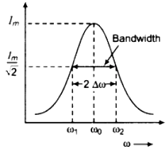
The figure shows the variation of current amplitude Im in a series LCR circuit with angular frequency value of R. The current amplitude Im in a series LCR circuit is given by
Im = \(\frac{V_{m}}{\sqrt{R^{2}+\left(\omega L-\frac{1}{\omega C}\right)^{2}}}\)

The current amplitude has a peak value at the resonant frequency that is when ω = ω0 = \(\frac{1}{\sqrt{L C}}\) other value of to, the value of current is less than the maximum value. As is clear from the figure that as the resistance in the circuit is reduced, the resonance curve becomes sharper. The more quickly the current amplitude (Im) falls for changes of frequency on both sides of resonant frequency (ω0), the sharper is said to be resonance. The sharpness of resonance of a circuit is described by its quality factor, Q also known as Q-factor.
It is defined as the ratio of the series resonant frequency to the difference taken between the two frequencies on both sides of resonant frequency such that at each of these frequencies, the current amplitude is 1/2 times its maximum value.
Mathematically it is given by
Q = \(\frac{\omega_{0}}{\omega_{1}-\omega_{2}}=\frac{\omega_{0}}{2 \Delta \omega}\)
The difference ω1 – ω2 = 2Δω is termed as the bandwidth of the circuit.
The smaller the value of Δω , the sharper is the resonance.
here, ω1 = ω0 + Δω
and ω2 = ω0 – Δω
Thus ω1 – ω2 = 2Δω
Q is a dimensionless quantity.
Let us now derive the expression for the Q-factor.
At Δ = ω1 and ω2


