Construction and working of transformer: Principle:
The principle of transformer is the mutual induction between two coils. That is, when an electric current passing through a coil changes with time, an emf is induced in the neighbouring coil.
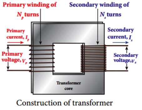
Construction:
In the simple construction of transformers, there are two coils of high mutual inductance wound over the same transformer core. The core is generally laminated and is made up of a good magnetic material like silicon steel. Coils are electrically insulated but magnetically linked via transformer core.
The coil across which alternating voltage is applied is called primary coil P and the coil from which output power is drawn out is called secondary coil S. The assembled core and coils are kept in a container which is filled with suitable medium for better insulation and cooling purpose.
Working:
If the primary’ coil is connected to a source of alternating voltage, an alternating magnetic flux is set up in the laminated core. If there is no magnetic flux leakage, then whole of magnetic flux linked with primary coil is also linked with secondary coif This means that rate at which magnetic flux changes through each turn is same for both primary and secondary coils. As a result of flux change, emf is induced in both primary and secondary coils. The emf induced in the primary coil εp is almost equal and opposite to the applied voltage υp and is given by

The frequency of alternating magnetic flux in the core is same as the frequency of the applied voltage. Therefore, induced emf in secondary will also have same frequency as that of applied voltage. The emf induced in the secondary coil eg is given by

where Np and Ns are the number of turns in the primary and secondary coil, respectively. If the secondary circuit is open, then εs =υs where υs is the voltage across secondary coil.

From equation (1) and (2),

This constant K is known as voltage transformation ratio. For an ideal transformer, Input power υp ip = Output power υs is where iυp and is are the currents in the primary and secondary coil respectively. Therefore,

Equation (4) is written in terms of amplitude of corresponding quantities,

(i) If Ns > Np ( or K > 1)
∴ Vs > Vp and Is < Ip .
This is sthe case of step-up transformer in which voltage is decreased and the corresponding current is decreased.
(ii) If Ns < Np (or K < 1)
∴ Vs < Vp and Is > Ip
This is step-down transformer where voltage is decreased and the current is increased.


