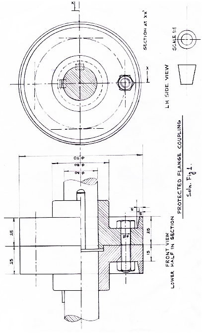
ASSEMBLY OF PROTECTED FLANGE COUPLING
(a) FRONT VIEW, LOWER HALF IN SECTION
Drawing lower half of both flanges with hatching.
Drawing both shafts with conventional ends.
Drawing both keys as per given positions.
Drawing nut-bolt assembly in lower half.
Drawing upper half of both flanges.
(b) SIDE VIEW, VIEWING FROM THE LEFT-HAND SIDE
Drawing six circles(3) with hatching(1) in shaft as per convention
Drawing pitch circle diameter and at least one nut-bolt in lower half.
Drawing both keys with cutting plane.
(c) DETAILS
Printing title (1), scale used (1), drawing projection symbol (1) and printing six dimensions (3).